
UTILITY GIS / EXPOSED-INFRASTRUCTURE EVIDENCE
RTK, GIS and Geo-Located Point Clouds for Utility Infrastructure
Emlid RTK receivers support coordinate-based utility surveying and asset mapping. Complementary photogrammetry can document exposed utilities in three dimensions, adding visual context to survey points, vector features and GIS attributes without replacing required investigation or professional responsibilities.
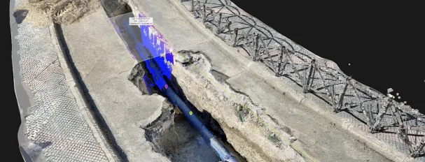
Observed data, configuration and quality evidence remain attached through handover.
01 / PRACTICAL OVERVIEW
Where Utility asset mapping and GPC fits in the working system.
Accurate utility records depend on more than knowing the approximate location of a pipe. Owners and contractors need usable spatial information that identifies assets, records attributes and preserves a traceable account of conditions encountered during construction.
When correctly combined, survey measurements, vectorised utility information and geo-located point clouds can form a more informative digital record. Each layer has a different evidentiary role: GNSS observes positions, photogrammetry reconstructs visible surfaces, and GIS interpretation assigns asset meaning and attributes.
02 / THE DIGITAL RECORD
Build complementary layers rather than one ambiguous file.
| Record layer | Typical content | Creation method | Key limitation |
|---|---|---|---|
| Surveyed geometry | Points, lines, levels and control | GNSS/RTK and other appropriate survey methods | Observation quality, datum and professional scope |
| Asset attributes | Asset ID, type, material, diameter, status and notes | Field codes, records and verified attribution | Incomplete or unverified source information |
| Geo-located point cloud | Visible pipes, chambers, trench walls and context | Photogrammetry or another suitable 3D capture method | Line of sight, coverage, georeferencing and reconstruction |
| Interpreted GIS/CAD | Utility features and as-built representation | Vectorisation and project review | Interpretation is not automatically certified |
| QA and exceptions | Checks, reports, coverage gaps and metadata | Independent verification and documented review | Must be planned; not generated by visual quality alone |
03 / FIELD-TO-HANDOVER WORKFLOW
Coordinate the record before backfill.
01 / Define scope and responsibility
Identify utility types, exposure windows, required survey standards, GPC applicability, attributes, coordinates, outputs and acceptance responsibility.
02 / Survey and attribute
Collect required points and lines using an appropriate correction and QA route. Record verified attributes and distinguish observed from supplied information.
03 / Capture visible context
Where suitable, use RX2 + PIX4Dcatch or another capture method to record exposed surfaces before concealment. Note inaccessible areas.
04 / Process and vectorise
Reconstruct supported imagery, inspect completeness and georeferencing, then extract agreed features without inventing hidden geometry.
05 / Verify and maintain
Check independent control, review metadata and exceptions, and deliver files in a structure the owner can retain and update.
04 / APPLICATIONS
Where the combined record is useful.
Utility asset inventory
Map visible valves, hydrants, chambers and surface features with consistent asset identifiers and inspection notes.
Exposed trench documentation
Preserve pipe arrangement, connections, levels where observed, and surrounding excavation context before reinstatement.
Construction as-built records
Support discrepancy review and record updates with traceable spatial evidence and appropriately scoped interpretation.
Future maintenance and coordination
Give authorised teams a reusable record for planning and investigation, with dates, coverage and limitations retained.
05 / SINGAPORE REQUIREMENTS
Separate GPC creation from utility-survey obligations.
- URA/IPAG context
- URA’s Major Infrastructure Workflow and enhanced site-investigation material should be assessed separately from the utility-survey standards and contractual obligations applying to a particular project.
- No automatic compliance
- GPC creation does not automatically satisfy USS, URA/IPAG, ASCE 38, PAS 128, cadastral or certification requirements. Applicability and acceptance must be confirmed for the project.
- Subsurface investigation
- Non-invasive detection and required utility surveys address questions that visible-light GPC cannot. Photogrammetry does not detect pipes behind intact ground or concrete.
- Professional responsibility
- Observed data, interpreted GIS/BIM information, certified drawings and regulated survey work are distinct outputs and responsibilities.
06 / DATA HANDOVER
Make the evidence usable after the project team changes.
A practical handover can include survey vectors, attribute schema, georeferenced point cloud and mesh, source imagery where agreed, coordinate/height metadata, processing reports, independent checks and a list of exceptions. File naming and retention should follow the owner’s information-management requirements.
Easepect can scope field collection, mobile GPC, processing and training around an approved representative exercise. Sensitive project information, agency details and identifiable site material are not requested through the general enquiry form and are published only with permission.
07 / FREQUENTLY ASKED QUESTIONS
Before choosing Utility asset mapping and GPC.
No. GPC can supplement required survey observations and records. The applicable investigation, utility survey, professional certification and contractual obligations remain separate.
No. Visible-light photogrammetry documents exposed visible surfaces. Appropriate subsurface investigation is required for assets that remain hidden.
Geometry alone does not reliably communicate asset ID, material, diameter, status, ownership or inspection notes. Attributes support asset management and must be verified rather than inferred solely from appearance.
No. URA/IPAG-related GPC requirements and other utility survey or contractual standards must be assessed separately. Capture technology alone does not establish applicability or acceptance.
RX2 is a strong candidate for lightweight asset collection and supported PIX4Dcatch iOS capture. RS4 or RS3 may suit teams that also need base/rover surveying. The required observation and correction workflow should drive selection.
LOCAL IMPLEMENTATION / SINGAPORE
Not sure which Emlid receiver suits your project?
Tell us what you are surveying, your operating environment and required deliverables. Model selection is optional; Easepect can help identify a suitable hardware and software workflow.